Introduction
Quartz is the basic material for all kinds of quartz resonators, quartz filters and quartz oscillators. A large part of the earth’s crust consists of natural quartz rock, which in its pure form is also called deep quartz or α-quartz. Quartz is composed of an ideal crystal lattice, which is made up of silicon and oxygen atoms in a perfect symmetry.
This crystal lattice gives quartz the important property that an electrical voltage can be measured at the ends of a quartz crystal as soon as mechanical pressure is applied to the crystal. Similarly, the crystal deforms when an electrical voltage is applied to its ends from the outside. This behavior makes it an ideal raw material for use in electrical circuits in the form of an oscillating quartz. In the past quartz was obtained by mining natural quartz crystals today artificially produced quartz of extremely high purity is used almost exclusively.
In every wristwatch (quartz watch), for example, a small plate of quartz material ensures that the second hand moves forward reliably and always evenly once every second.
Quartz as a raw material

Quartz is a mineral consisting of silicon and oxygen with the chemical formula SiO2. The crystalline form of quartz is relatively common in nature, but in the high purity form, which is required for the production of quartz crystals, the supply is rather small. The limited supply and high cost of natural quartz has led to the development of a synthetic quartz manufacturing industry since the 1960s. Synthetic quartz crystals are produced in vertical autoclaves.
The autoclave works on the principle of hydrothermal gradients with temperatures of over 400 °C and pressures of over 1,000 bar. So-called seeds are placed in the upper chamber of the autoclave, while natural quartz (laskas) is placed in the lower chamber. Then an alkaline solution is poured in, which increases the pressure in the chamber by heating. The heating of the autoclave creates a lower temperature in the upper chamber compared to the lower one. This temperature gradient creates convection of the alkaline solution, which dissolves the natural quartz at the bottom of the chamber and deposits it on the seed crystals in the upper section. Crystals produced by this method can have a mass of several hundred grams and can be grown in a few weeks. The slower the crystals grow, the higher is their purity and quality.
Piezoelectric effect

Piezocrystals are crystals with polar axes but without a center of symmetry. These include, for example, α-quartz or zinc sulfide.
By an externally applied electric field, the deformation of a whole piezoelectric crystal can be achieved, which is sometimes called inverse piezoelectric effect.
The piezoelectric effect can be explained by a shift in the positive and negative charges of the silicon and oxygen ions when pressure is applied, creating an electric dipole moment:
When an insulator with a polar axis, i.e., a macroscopic dipole moment, is placed in an electric field, the charges in it shift and mechanical deformation occurs. Conversely, a mechanical deformation can shift or align the charges to create an electric polarization, i.e., an electric field. The piezoelectric field E, as well as the voltage U generated between the end faces, are proportional to the relative deformation ε = Δx / x:

or

U=Ex=δΔx
Here δ is called the piezoelectric coefficient, which is material dependent. The deformation is due to the fact that dipoles, which lie behind each other in the field direction, attract each other. Adjacent layers are brought closer together by these forces until elastic counterforces compensate for the electrical forces.
The charges occur at the ends of the polar axes and are shifted against each other by deformation in their plane, resulting in surface charges at the interface of the overall neutral crystal.
The crystal thus undergoes an electric polarization due to the deformation, which corresponds to the polarization of the dielectrics in the electric field.
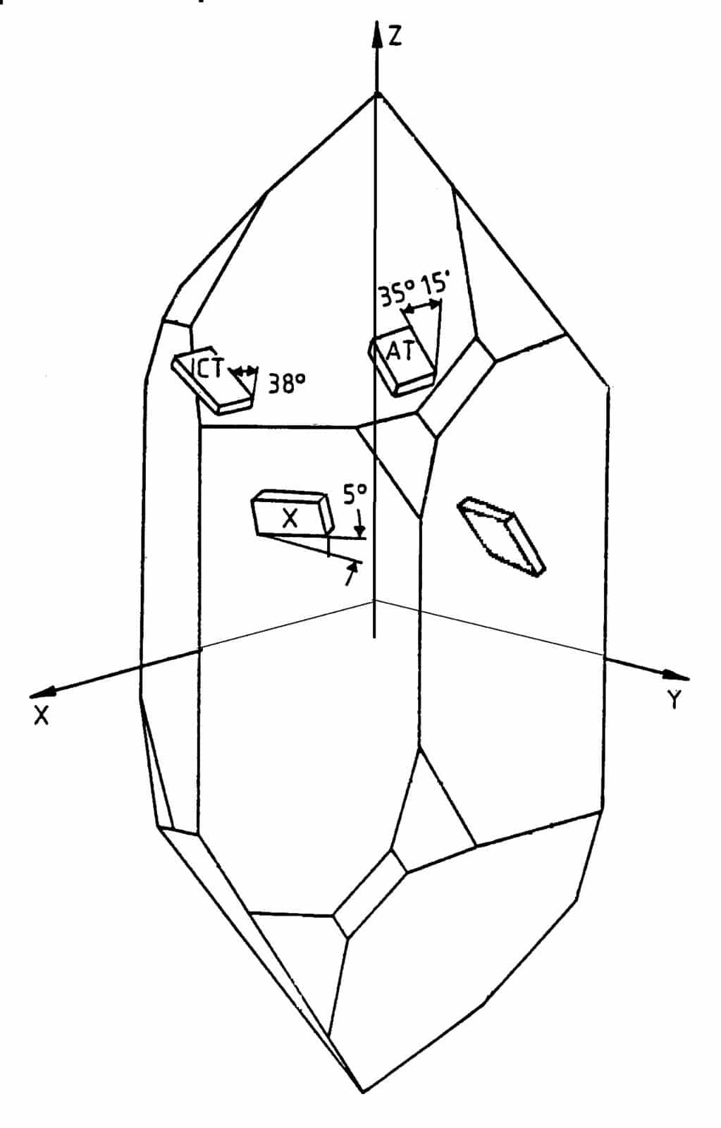
Cut angle

The properties of the piezoelectric effect depend strongly on the orientation in which the force or voltage acts on the quartz crystal. Also, the ambient temperature has different effects depending on the direction. Different quartz crystal cuts can be made, which have different properties. Usually, the different quartz cuts are defined by two rotation angles
and
around the crystallographic axes.
The most common cuts are the single rotation AT cut (= 0° ) and the double rotation SC cut(
= 22° ). The theta angle is about 34° in both cases.
There are also other double rotated cuts like MSC-, IT-, FC-, LD- for special applications.
Oscillating Quartz

The active component of the crystal resonator is a mechanically vibrating plate (“crystal element”) cut from mono-crystalline quartz with a precise orientation to the crystallographic axes. The resonator is plated under high vacuum with aluminium, silver or gold electrodes and hermetically sealed into a suitable enclosure either with a cold-weld or resistance weld process.
The physical dimensions of the element and its orientation to the axes will determine in particular the resonance frequency, its initial accuracy, its electrical properties and the temperature coefficient.
The frequency of crystals is inversely proportional to the thickness of the element. For mechanical processing, this results in an upper frequency limit of about 50MHz for crystals operating on the fundamental mode.
Inverted-Mesa-Crystals

To achieve higher frequencies in the fundamental, chemically etched so-called inverted mesa crystals also exist, in which the central part of the resonator is etched so that it is only a few micrometers thick.
Many different parameters have an influence on the final resonator properties. Thickness and diameter of the element, electrode diameter, electrode material, but also fixtures, sealing method, etc.
Crystal elements can be made plane-parallel or contoured (with chamfers, plane-convex or bi-convex).
Contouring is necessary to avoid edge effects. A radius of curvature can be made on one or both sides of the crystal element to concentrate the energy in the center of the resonator.
Overtones

High frequency crystals vibrate in the thickness-shear vibration, which can be excited in fundamental or odd overtone modes.
The motional capacitance C1n of an overtone-crystal decreases with the order n of the overtone and is approximately given by
Therefore, the ratio CO/C1 is much larger for overtone crystals than for crystals operating in fundamental mode and the pulling range is reduced by a factor of approximately n3. Crystals used in VCXOs, where wide pulling range is required, therefore operate in fundamental mode..
Overtone Quartz

All crystal resonators produce a main mode which is a thickness shear vibration and also unwanted responses, which are inharmonic thickness shear modes above the resonance frequency.
Besides the commonly used thickness shear C-mode another thickness shear mode named B-mode exist. It has a higher frequency and commonly lower motional resistance than the C-mode but a larger temperature coefficient. Sometimes it becomes necessary to filter this mode for the oscillator to work on the C-mode.
Further unwanted modes are shear-, flexure-, thickness- and twist vibrations, which can appear above and below the required resonance frequency. With correct oscillator design the unwanted modes rarely cause problems. Unwanted modes close to the resonance frequency affect the start-up behaviour of oscillators, or cause shifting to the wrong frequency during operation.
Other undesired effects are frequency and resistance dips over temperature caused by unwanted modes. Spurious modes are generally specified as the ratio of resonance resistance of the inharmonic modes to the main mode resistance.
Equivalent electrical circuit

Near the resonant frequency, the crystal unit is represented by an electric two-pole. The circuit resulting from the equivalent circuit diagram reproduces the electrical behavior of the oscillating crystal.
Shunt capacitance CO: Capacitance between the electrodes, crystal holder, leads and case. Typically 1-50 pF
Dynamic capacitance C1: represents the mechanical elasticity. Typically 10-12 – 10-18 F
Dynamic inductance L1: represents the mechanical inertia. Typically 10-3 – 10-5 H Dynamic resistance R1: represents mechanical losses. Typically 1 – 105 Ω
Pullability

The pullability is the ability to change the frequency of a crystal unit from the natural resonant frequency (fs) to a load resonant frequency (fL). In addition to the components of the equivalent circuit, an external capacitance known as the load capacitance CL needs to be provided within the electronic circuit design for the crystal to vibrate on its resonant frequency.
A decrease in load capacitance causes an increase in frequency, and an increase in load capacitance causes a decrease in frequency
With a load capacitance in series to the crystal the resonance frequency is shifted according to:
and the resistance at resonance becomes:
Temperature coefficient

The resonant frequency of oscillating crystals generally depends on the temperature of the quartz. The temperature characteristics of AT- and SC-cuts crystals are described by a 3rd order parabola.
It is then possible to describe the relative change of frequency:
with
Ti is the inflection temperature.
Frequency Temperature
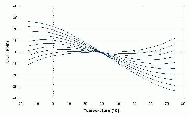
The frequency-temperature characteristic is primaraly determined by the the cut angle. For a given cut the parameter which changes the most with θ angle is Ai.
Ci is almost constant and Ti varies between +25°C and +35°C for the AT-cut and between +85°C and +95°C for the SC-cut , depending on the dimensions of the crystal element .
SC-Cut

Since the inflection point of the SC-cut is close to 90° it is very suitable for ovenized oscillators because a turn over point around 80° leads to very low dependency of frequency against temperature.
Moreover SC-cut crystals are less sensitive to mechanical and thermal stress and provide lower aging and higher Q compared to the AT-cut.
Aging

Aging is the change in the eigenfrequency of the oscillating crystal with time. It can generally be represented as an inverse logarithmic function. Aging is affected by the manufacturing technology, pre-aging, design of the oscillator, and environmental conditions.
The application of the metallic electrodes to the quartz material changes the total mass of the oscillating crystal and thus its eigenfrequency. Oxidation effects or accumulation of foreign matter on the electrode material can further change the electrode mass over time. The surface of the quartz material and the vapor-deposited metal layers form a porous surface to which foreign substances can easily adhere. This effect can be reduced by filling the quartz housing with an inert gas mixture of nitrogen and helium. Nevertheless, outgassing, for example, from the glued areas of the quartz on the quartz holder can lead to time-dependent aging effects.
Mechanical forces (mechanical stress) acting on the quartz also lead to aging effects. The quartz crystal itself consists of a highly ordered crystal lattice. Machining processes during production such as sawing, grinding or polishing partially disrupt these crystal lattices, which can change the physical properties of the quartz material. Relaxation effects in the crystal lattice remove these imperfections or lattice defects over time, resulting in a change in frequency (aging). The suspension of the quartz in the housing also leads to a mechanical load to which the quartz material must adapt. The connection of quartz holder, conductive adhesive and quartz adapt to each other better and better in the course of operation, whereby after a certain run-in period only small changes in the resonant frequency are noticeable and a quasi-stable condition is established.
Typical aging values of an oscillating crystal in the first year are:
Resistance-welded packages: 1 – 5 ppm/yr. Cold-welded packages: 0.05 – 1 ppm/yr.
Drive Level Dependence

Level dependence is the dependence of the resonant frequency on the power conducted through the oscillating crystal.
By changing the level, the resonance and phase curves change. There is usually a linear dependence of the resonant frequency with the power.
The effect is on the order of about 10-9/µWatt and is usually less for a crystal in the SC cut than for the AT cut. Problems occur especially
if the level fluctuates or drifts with time. In general, oscillating crystals should always be driven at the level for which they were designed and built. Higher drive levels excite unwanted oscillation modes, cause serious degradation of the frequency-temperature characteristic, accelerate aging, and can shift frequency due to resonator overheating. Complete destruction of the crystal due to overload is also possible.
Activity Dips

A dip is characterized by a deviation from the third-order frequency-temperature curve. Dips can cause problems especially in crystals for TCXOs, since they are operated in a wide temperature range.
An activity dip is caused by the excitation of unwanted modes by mechanical coupling. Here, two different modes have different temperature behavior, which cross at a certain temperature. At this point, the vibrational energy is partially transferred from the desired mode to an undesired mode. The dips are influenced by the design of the resonator, the drive level and the conditions of the oscillator circuit.